How to Configure WPD Plotting in Sign Wizard 4 on Windows XP
WPD stands for Windows Printer Driver. WPD ports are a way to connect to a cutter using the Windows printer
driver subsystem, which can solve certain plotting problems.
Here are the steps you need to take to configure this type of port.
-
Go to Start and Devices and Printers.
-
Press Add a Printer on the left side.
-
Press Next
-
Check Local printer attached to this computer
-
Uncheck Automatically Detect and install my Plug and Play printer
-
Under Use the following port, select the port your cutter is attached to.
-
Press Next
-
Under Manufacturer, select Generic
-
Under Printers, select Generic / Text Only
-
Press Next
-
Give a name to your printer (really a cutter), such as the make and model of your cutter.
-
Press Next
-
Do not print a test page
-
Press Next
-
Press Finish
-
The driver will be installed into Windows.
-
Launch Plot Manager with the F2 key or File | Plot. Depending on your version, you may need to have some
object selected first.
-
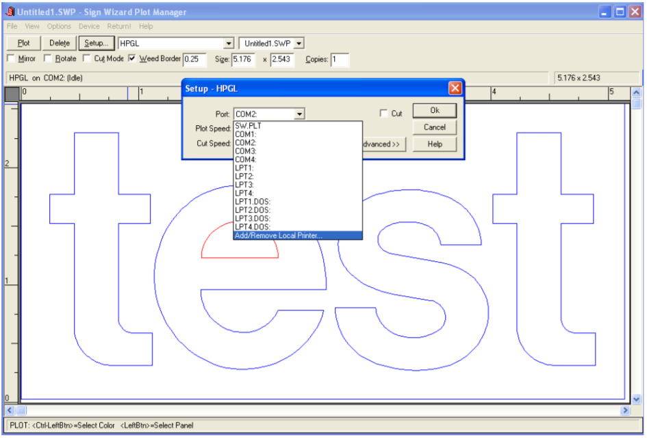
Select the port drop down list in Plot Manager and select Add/Remove Printer Port:
-
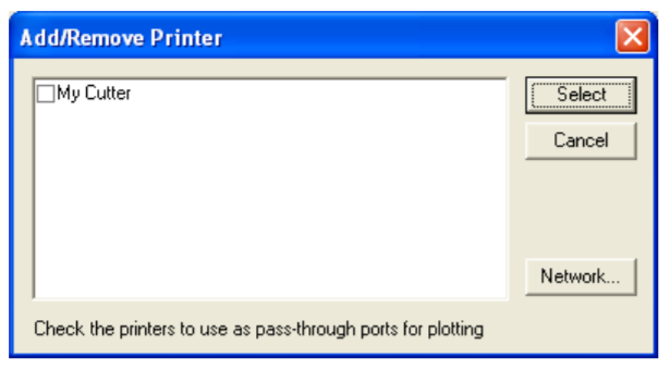
This dialog box will appear:
-
If you’ve installed a driver from your cutter’s manufacturer or followed the steps above, it will appear in this window and you can place a checkmark next to it as shown above. Place a checkmark next to the cutter you
want to use, and press Select.
-
If the new WPD port is USB or LPT (parallel), there’s nothing else to be done and you can proceed to cutting. If
it’s a COM (serial) port, you will need to go into Control Panel to make sure the configuration matches the
cutter’s configuration. With USB to serial converters, there will be a COM port listed that you can select.
-
If using a COM (serial) port:
- Right click on My Computer on the desktop
- Select Manage
- Select Device Manager
- Open the Ports section
- Double-click on a “Communications Port”
- Select the Port Settings tab
- Make sure these port settings match your cutter’s settings. The standard settings are 9600, 8, N (None),1, and Flow Control set to Xoff/Xoff. If you can’t view your cutter’s settings, the above settings should work.
- The Flow Control MUST match what the cutter is using, otherwise you will get bad cuts.
-
Go back to Plot Manager and make sure the new printer you’ve configured is selected as the current port in the
Setup dialog box.
-
Do a test plot and make it has enough data to test the flow control, such as a few lines of text.

